Power Electronics · In Development · 2026 – Present
A custom sensorless BLDC ESC on a KiCad PCB — six-step commutation from back-EMF zero-crossings, a three-phase MOSFET inverter, gate drive with dead time, and current/temperature protection on a Teensy 4.1.
- Role
- Sole designer & firmware developer
- Team
- Individual
- Status
- In Development
- Timeline
- 2026 – Present
Problem Statement
A brushless DC motor needs timed commutation on three phases. Hall sensors make that easy, but they add cost, wiring, and another failure point.
This controller is sensorless: it watches the back-EMF on the floating phase, detects zero-crossings, and advances a six-step sequence from that timing. The board is a full ESC-style stack — buck supply, gate driver, MOSFET bridge, sensing, and a Teensy 4.1 — laid out in KiCad so bring-up happens on one PCB instead of a rat’s nest of modules.
Design Goals
- Six-step sensorless commutation from back-EMF zero-crossings
- Gate drive with intentional dead time so high- and low-side FETs never shoot through
- Over-current and over-temperature protection into the Teensy ADC
- ~20 kHz PWM for small BLDC motors
- Layout that keeps switching noise out of the BEMF and current-sense paths
- Probe-friendly test points for scope bring-up
System Architecture
- Power stage — six N-channel MOSFETs as three half-bridges (QHA/QLA … QHC/QLC) feeding PHASE_A / B / C
- Gate driver — translates Teensy PWM (
AH/AL,BH/BL,CH/CL) into high-/low-side gate drive with bootstrap caps - Back-EMF sense — per-phase resistor dividers (plus clamp/filter) into
BEMF_A/B/Cso the MCU can find floating-phase zero-crossings without Hall sensors - Current sense — low-side shunt on
BRIDGE_RETURNinto an INA180 →CURRENT_SENSE - Temperature sense — NTC divider →
TEMP_SENSE - Supplies — LM2596S-5 buck for +5 V, local 3.3 V for logic; Teensy 4.1 runs the timers, ADC, and commutation state machine
In six-step sensorless mode, two phases are driven and the third floats. The floating phase’s back-EMF crosses a virtual midpoint; after the usual ~30° electrical delay, the firmware advances the next step. Open-loop start-up gets the rotor moving until back-EMF is large enough to trust.
PCB Layout
The board is laid out as mixed-signal power electronics: noisy bridge on one side, quiet control on the other.
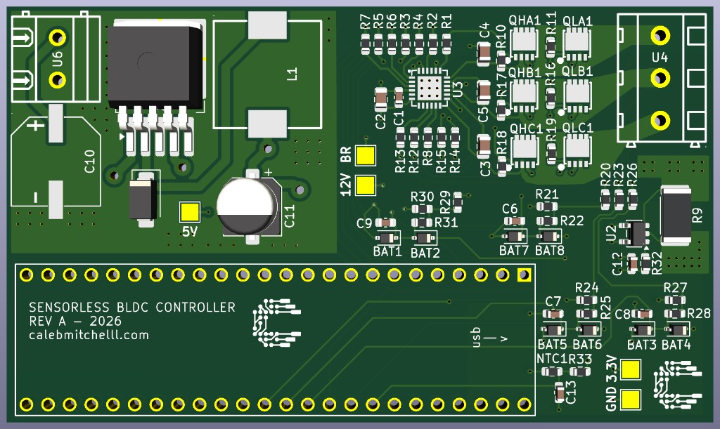
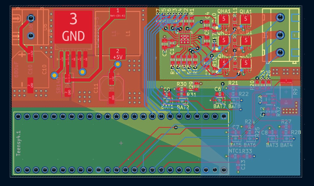
Final design — Top edge holds the battery input, bulk cap, and LM2596 buck. Right side is the gate driver, six MOSFETs, and phase terminals. Bottom edge is the Teensy 4.1 footprint with USB facing outward. Silkscreen calls out Rev A / 2026 and test pads for 12 V bridge, 5 V, 3.3 V, and GND.
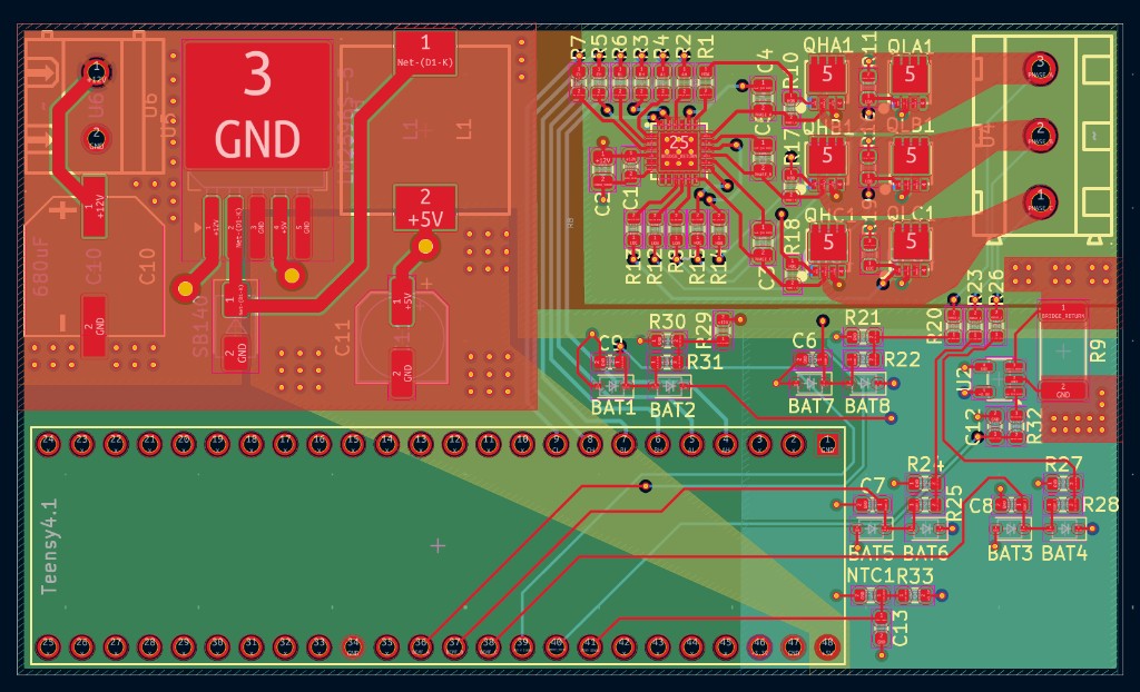
Top layer (red) — Pads and short signal runs: Teensy → gate-driver inputs, local gate resistors, and the denser BEMF/passive neighborhood. Keeps digital edges short so they do not wander across the power plane.
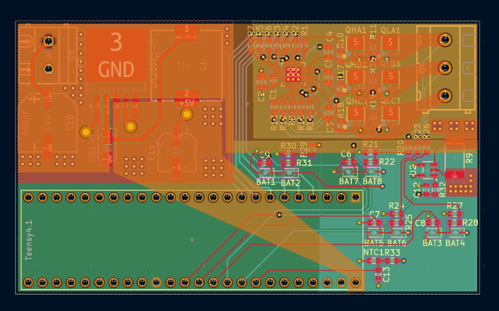
Power layer (orange) — Fat copper for VIN and the bridge rail. Motor current needs low resistance and low inductance from the input cap to the FET drains; skinny traces there would heat up and ring on every commutation edge.
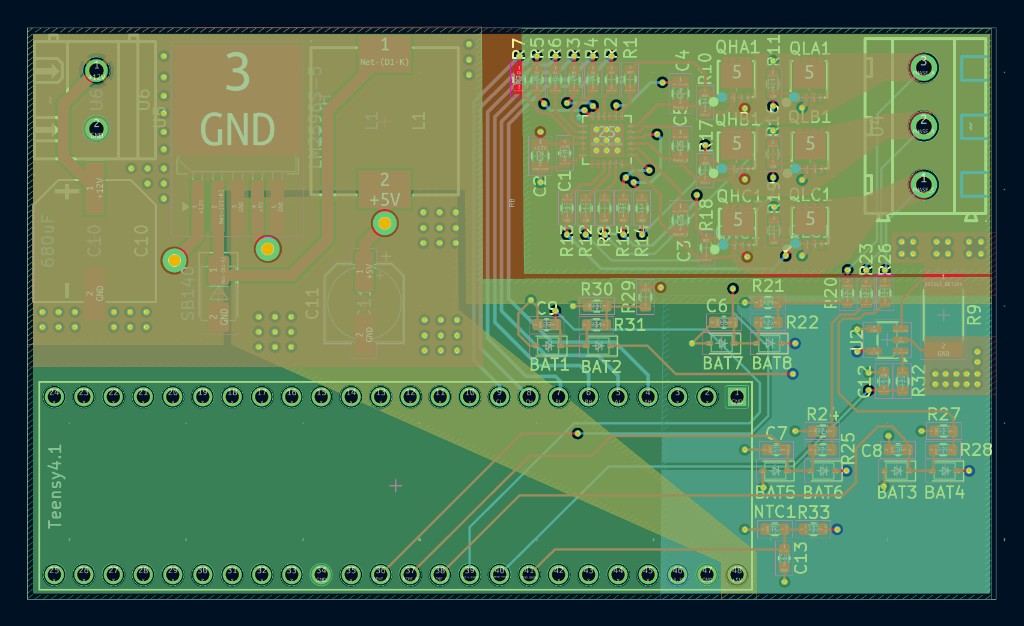
Ground layer (green) — Two grounds on purpose:
- Power / bridge ground under the MOSFETs and gate driver (return for high di/dt switching)
- Logic ground under the Teensy and buck control side (quiet reference for ADC and digital)
They meet at a single star point through the sense shunt path (BRIDGE_RETURN ↔ GND) instead of sharing a pour. That way bridge return current does not modulate the Teensy’s ground and corrupt BEMF / current readings.
Bottom layer (blue) — Leftover signal and sense routing: BEMF divider returns, ADC nets, and cross-unders that would fight the top-layer breakout under the Teensy.
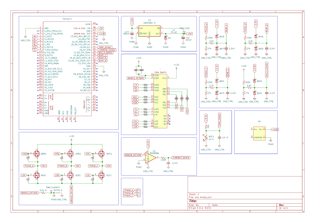
Schematic — Same blocks on paper: Teensy, buck, gate driver, three-phase bridge, BEMF dividers, INA180 current sense, NTC temp sense, and labeled test points.
Hardware Design
Key parts on the board:
- Teensy 4.1 — PWM timers + ADC for commutation and protection
- LM2596S-5 — steps battery voltage down to 5 V for logic / peripheral rails
- Gate driver + bootstrap — high-side drive without a separate isolated supply per phase
- Six discrete MOSFETs — inspectable, probeable three-phase inverter
- BEMF dividers — scale phase voltage into Teensy-safe ADC range with light RC filtering
- 0.01 Ω shunt + INA180A1 — bus current into
CURRENT_SENSE - NTC — board temperature into
TEMP_SENSE
The interactive 3D model on this page is the KiCad board export.
Software Design
Firmware loop (in progress):
- Complementary PWM with dead time on the six gate channels
- ADC sampling of BEMF, bus current, and temperature
- Zero-crossing detect on the floating phase → commutation advance
- Fault paths for over-current / over-temperature
Start open-loop, then hand off to closed-loop sensorless tracking once back-EMF amplitude is usable.
Engineering Decisions
- Six-step + back-EMF instead of FOC first — clearer bring-up and easier to see on a scope
- Teensy 4.1 — fast timers, lots of PWM, quick iteration on the bench
- Split grounds — treat the bridge as a noise source; keep the MCU reference clean for sensing
- Discrete FETs — easier to probe and swap during prototype than a fully integrated module
Testing and Validation
Planned / in-progress:
- Gate waveforms and dead-time check on a scope
- Back-EMF capture on a spinning motor
- Current-limit trip with a current-limited supply
- Thermal behavior under load
Results
Hardware design (schematic + multilayer layout + 3D board model) is complete. Firmware bring-up is in progress — open-loop spin-up first, then closed-loop zero-crossing tracking.
Challenges
- Separating real BEMF zero-crossings from PWM switching junk
- Getting through start-up before back-EMF is large enough to sense
- Keeping layout inductance low at the switching nodes without coupling noise into the Teensy
Lessons Learned
Sensorless control is as much a grounding and layout problem as a firmware problem. If the ADC reference bounces with every FET edge, no amount of clever zero-crossing code will save you.
Future Improvements
- Closed-loop speed regulation
- Soft-start and stall detection
- Assembled-board photos and scope captures from bring-up
- Optional FOC path once six-step is solid
Gallery
Questions about this project? Email Caleb.